
Electronics
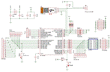
Electronics Electonic part consists of two blocks: controller board and four boards with
photointerrupters. Controller part is based on PIC18F4550 microcontroller by
Microchip, which has built-in USB support. Quartz X1, capacitors C1-C5,
and resistor R23 are the standard components for microcontroller.
SW1 switch sets MIDI channel. Resistors after PORTD limits a source charge
current of MOSFETs. Resistor pack RX2 pull-up MOSFET sources to the ground.
The rest pins of the microcontroller are connected to PLS connectors for additional components (variable resistors, encoders, LCD etc.). The J7 connector is intende for power supply of these components.
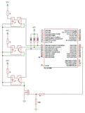
At the picture left there is a connection ciruit of three photointerrupters
of the same group.
Photointerrupter transistors's emmiters are tied to the ground net of the respective board. The collectors of ones are tied to output headers. These headers of all four boards are tied to PORTB of PIC. So, if the photointerrupter board is powered (i.e. if MOSFET it tied is opened) and one of the keys is pressed, i.e. there is no shutter in photointerrupter, then phototransistor pulls the respective PORTB pin up to the GND net. If the key is released and it's shutter cuts the light, then the phototransistor is closed and there is logic one at the PORTB pin.
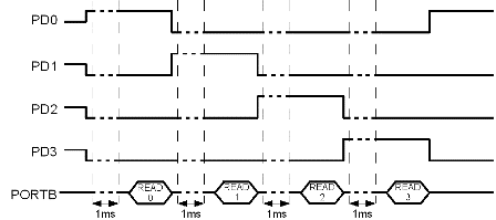
Working algorithmAfter the power turned on, PORTD is set as output, PORTC's free pins are set as inputs. 0th bit of the PORTD is set as 1, after that the 1ms pause is sustained. Then PORTB state is read, and a logic one is shifted to the next PORTD bit. This shifting is made by a ring, i.e. after 3rd bit the logic one will be thrown to the 0th one. After that we reset the TMR0 timer. Now we analyse a PORTB state, which was read before PORTD change. If i-th bit of PORTB has changed it's value (relative to the previous scanning)from 1 to 0, then the key corresponding to this bit and the board previously activated was pressed. If the value has changed from 0 to 1, then the key was released. In this case, we try to send a data through USB. If data were transmitted succesfully, then we keep it in mind. If after analysing of every eight keys the untransmitted data remained, then have a secong go and try to send data for the keys, whose data were not transmitted. If all the keys were processed, then wait, until the TMR0 will tick 1ms since the ordinal octade was turned on, read PORTB, shift a logic one etc. at the infinite cycle.It is necessary to explain what means "wait 1ms". All user actions are in ServiceRequests procedure, which is periodically called by the main controller's program. This program also services the USB protocol, so we cann't stay too long at the ServiceRequests procedure. Therefore, at the waiting process, at the each entry to the ServiceRequests we check if the 1ms has elapsed and escapes if it is false. ConstructionThe main board is made of one-side glass fiber laminate 84x74mm. Photointerrupter's boards are made of the only piece 282x162mm, which is then cut to four boards. For connection to the main board the two 16-wire ribbon cables are used. On the first one, the five IDC-16F headers are tied. Four of them are tied to photointerrupter boards and the fifth to the J1 header of the main board.
Ôàéëûprogr.zip - MPLAB project. pcb.zip - PROTEUS project. main.pdf - the main board, a file for a laser printer manufacturing method phints.pdf - photointerrupter boards parts.pdf - soldering map |
15.02.14
Even new springs 20.05.10
20.05.10
18.05.10
|

 Photointerrupters have a significat peculiarity: if there is no shutter, then
after the LED powering phototransistor opens with delay about 0.5ms. Therefore,
if we read the states of a regular photointerrupters octad straight away we turn
the one on, there is a danger "not to see" some of the keys pressed
(because the phototransistor is closed and there is a logic one at the PORTB
pin, as if the key is released). To avoid it, it is necessary to read PORTB with
1ms delay after we turned photointerrupter's board on. On passing, let's take
notice that when microcontroller's clock frequency is 20MHz 1ms is
20 000 000 / 4 / 1000 = 5000 operations, which can be used for PORTB state
analisys or data transmitting.
 The second cable is divided to the four wire couples, each one is tied to the
BLS-2 header, that is connected to power supply headers of the boards. Take your
attention that wire couples have different length. It is important not to
confuse what couples are longer and what are shorter (I had :-)